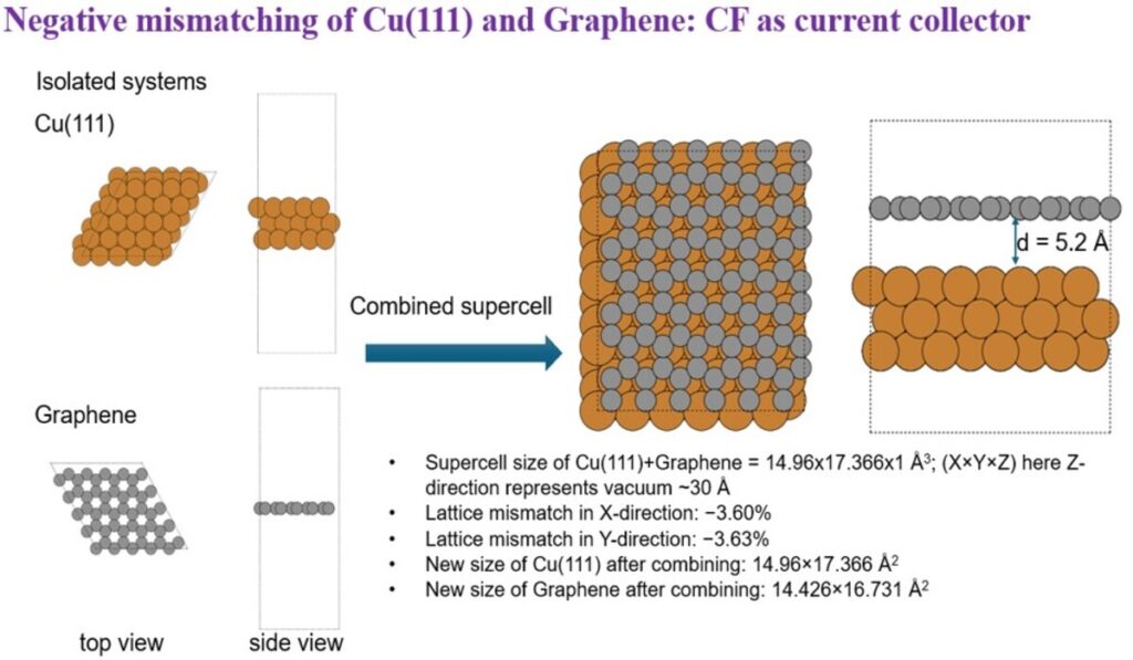
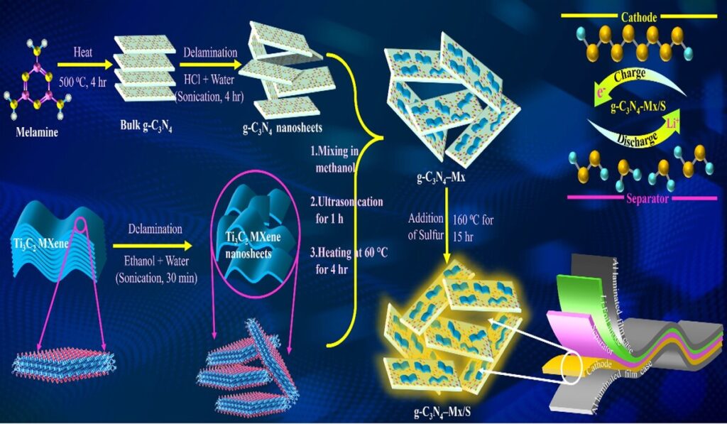
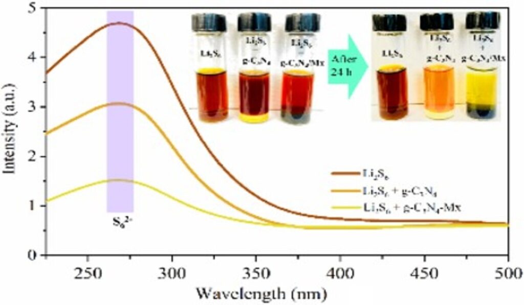
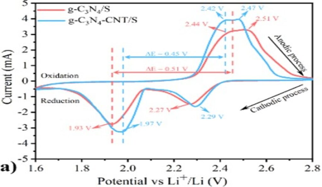
DFT explain that negative lattice mismatch of deposited layer (Graphite) is smaller than that of the substrate (Cu(111)), causing the deposited layer to stretch and accommodate the larger lattice of the substrate. Conversely, the substrate might compress slightly if the deposited film imposes a significant strainCarbon Fiber Based Stand-alone ElectrodesCarbon Fiber Based Stand-alone ElectrodesSchematic illustration for the synthesis of g-C3N4-Mx/S nanocomposite; Polysulfides degradation testCV curves of the prepared batteries
LFP battery
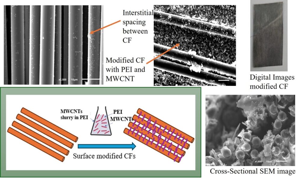
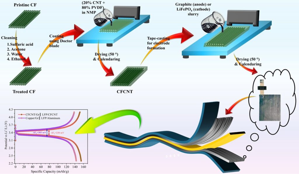
Schematic of the preparation and modification of CFCNT composite for use as a free-standing electrode
LNMO battery
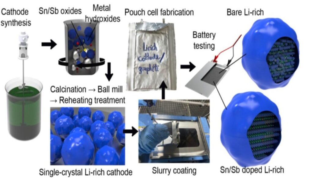
Flow chart for the synthesis of Li-rich cobalt-free cathode and pouch cell preparation.
Mined Graphite: Anode
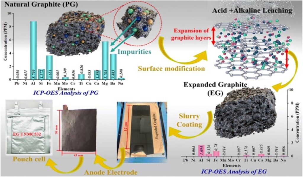
Schematic diagram showing the preparation of expanded holey graphite (EG) from pristine graphite (PG) and its pouch cell assembly.
Separator
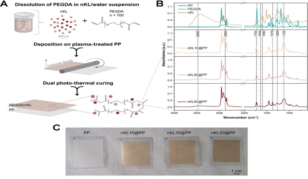
(A) Preparation scheme of PEGDA-lignin coated PP separator. (B) FTIR spectra and (C) digital picture of nKL10/nKL30/nKL50@PP after dual curing.
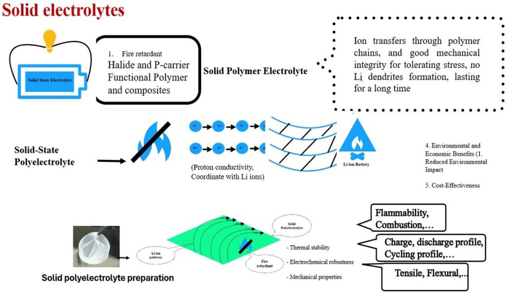
Quasi-solid electrolyte
Battery Evaluation & performance check
Theoretical Validation
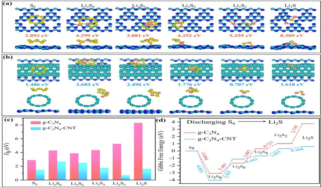
Figure: Optimized configurations of Lithium polysulfides on the surfaces of (a) CN and (b) the heterostructure of CNCNT. The yellow, pink, cyan, and blue spheres represent sulfur (S), lithium (Li), carbon (C), and nitrogen (N) atoms, respectively. Panel (c) displays the binding energies and panel (d) illustrates the relative free energy for the discharging process from S8 to Li2S on both CN and CNCNT surfaces.
Postmortem analysis: XPS
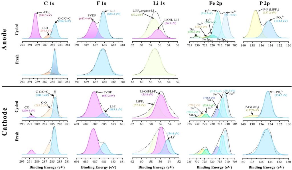
XPS spectra of graphite anode and LiFePO4 cathode harvested from the CFCNT/Gr||LFP/CFCNT full cell after 1st discharge and post 150 cycles.